Based upon a request, and seeing that the post might be handy to those who are thinking of exploring the exciting world of electronics, I am posting the design for a LED stroboscope which is done
here. Apologies in advance to samer and the rest of the moderators for posting the images in their current size, but to understand circuitry you have to see it and close-up shots are way better than thousands of lines of text. Referencing to links mean the post will be a series of text lines and will be tiring to read.
In this post, it is assumed that those with no background about electronics (at all) will gain some information about the components used for the design and will be able, hopefully, to use them in other designs. Some basic concepts like voltage, current, opened circuit, closed circuit, etc… have been already explained in the
post about the beetle bot, so they will not be tackled here.
Part 1: What Is a Stroboscope? What Are Its Applications?
A stroboscope or a strobe is a device used to show a cyclically moving object in slow motion or in stationary position. It is commonly used to study oscillating objects with known frequencies like vibrating machine parts. Usually a mark is set on the moving object as reference to track the motion and indicate the change in the object’s position.
The basic idea of the stroboscope is sampling, where a series of short and instantaneous samples (shots) are taken for an object in continuous motion such as oscillating objects. This phenomenon is also known as
temporal aliasing or
stroboscopic effect.
When the sampling frequency (the frequency for which the shots are taken, in our case the stroboscope’s frequency) is equal to the frequency of the moving object, the object appears to be stationary (the indication “Pulses” refers to the pulses of the sampling frequency):

However, when the sampling frequency is less than the frequency of the moving object, the object appears to be moving forward but in slow motion:

If it is greater, then the moving object appears to be moving backward in slow motion:

A stroboscope can also be used to measure the rotational speed of motors. This will be the application in which the designed stroboscope will be tested on. Unlike tachometers, which directly measure the speed, the stroboscope compares the speed of the motor with a known frequency (the sampling frequency that is set by the user).
Part 2: The LED Stroboscope: How Does It Work? How Can It Be Used to Measure Motor’s Speed?
Some stroboscopes are mechanical in nature while others are electric. The one in this design is electric where the sampling frequency is generated with an RC (ResistorCapacitor) circuit and regulated with a 555 timer (more on this later), and then fed to a bright LED (Light Emitting Diode) which begins flashing at the same rate as the sampling frequency. When the LED starts to flash at the same frequency of the rotating shaft of the motor, the shaft appears to be stationary. When this frequency is reached, it is possible to calculate the rotational speed of the motor in RPM according to this formula:
Motor_speed (RPM) = 60 x f_strobe
LEDs are used instead of incandescent bulbs (filament based lamps) since LEDs can cope with fast rates of flashing while the filament bulbs can’t (filament stays hot for a while after being powered off => it stays on => permanent light). So in order to build a LED stroboscope, it is required to build an oscillator circuit (generator of sampling frequency) and a driver circuit (flashing LED).
Part 3: Understanding The Basic Components
Before delving into the design, it is fundamental to understand the components which compose the circuits.
Breadboard
The platform onto which the circuit will be built is the breadboard:

This breadboard is actually a series of metallic rails that act as connecting terminals for the electronic components. It can come in two forms:
Form A: Two separate rails on top (sometimes marked “+” and “-“) followed by two 5-connected rails which are separated by a space in between.
Form B: Same as Form A but with additional two rails on the bottom (as seen in picture above).
In both forms, the two separate rails are used as voltage-distributing terminals to the remaining components on the board (from here on, they will be referred to as the voltage rails). The 5-connected rails are used for connecting components. The space in between is used to connect components that have multiple pins that should not be connected together unless otherwise needed. These components are the ICs or Integrated Chips; and example of an IC is the 555 timer.
To have a better understanding on the connection of the rails, a breadboard is opened and shown its bottom view:

Notice how the voltage rails are interconnected except at the middle where a gap is present:

This is due to the fact that in some designs, it is desired to have two voltage levels (e.g. 5V and 9V).
For the 5-rails components section, every 5 vertical pins are interconnected (in the close-up picture above, it can be seen that one of the metallic rails is removed to show the 5 vertical pins on the top surface of the breadboard). A picture of the rail’s form is shown here:
 Resistors and Potentiometers
A resistor is simply a device with two pins that resists the flow of current: the higher its resistance rating, the less current is passed through:
Forms of Resistors:

The operation of a resistor can be described as such (pictures captured from my first hands-on electronics book “Build Your Own Digital Door Alarm”):

The symbol of the resistor in an electronic circuit diagram is shown here:

A detailed explanation about their structure, color bands, nominal values, and networking (series and parallel) can be found
here.
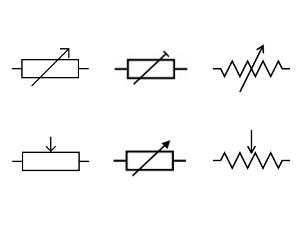
A potentiometer (or pot) is a variable resistor which typically has three pins: two for the resistor in between and one for the wiper. The wiper can hold a resistance value of zero to the maximum nominal resistance written on the side of the pot depending on the position of the trimmer (the screw in the middle that changes the resistance value of the pot). Some pots have more pins because they have multi-turn trimmers. Each time the trimmer is moved, the pot’s resistance changes by a step. The value of the step resistance depends on the nature of the pot (single turn or multi-turn), and the more resistance steps are needed, the more turns, trimmers and pins are required.
Forms of Potentiometers:

The symbol for the potentiometer on the electric diagram is shown here:
 Capacitors
A capacitor is a device that either blocks voltage, stores voltage, or filters out a signal. Capacitors have two pins, but they can have either one of two forms: bi-polar (otherwise known as non-polar) or mono-polar (otherwise known as polar or electrolytic). They consist of two parallel metallic plates and an insulator, called the dielectric, in between. The name of the capacitor depends on the nature of the dielectric (ceramic, mica, polyester, tantalum, etc…), and the shape depends on its polarity nature (mono-polar are usually cylindrical while bi-polar are either rectangular or disc-shaped).
Forms of Capacitors:

The operation of a capacitor can be described as such:

More details about capacitors can be found
here.
Diodes and LEDs
A diode is a device that acts like a one-way valve: it allows the conduction (passage) of electric current in one direction (from the negative cathode to the positive anode; diodes are usually marked with a ring on the direction where the cathode is):

The shape and size of the diode depends on the maximum allowed voltage/current.
Forms of Diodes:

The symbol of a diode in an electronic diagram is as such:

More info about diodes can be found
here.
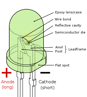
LEDs or Light Emitting Diodes are a special brand of diodes: they emit light once current passes through; this is due to the combination of the electrons from the current to the electron holes found on the anode:

The symbol of the LED is:
 Transistor
A transistor is usually a 3-pin device that acts like a current intensifier. The three pins correspond to three terminals: the collector, the base, and the emitter:

The transistor operates only when current is supplied to the base, and the current generated by the emitter is equal to that supplied to the collector multiplied by a constant factor.
The basic two forms are NPN (negative-positive-negative) and PNP (positive-negative-positive). The electronic symbol differs according to the type of transistor used (for this design, the BJT form is used):

Example of NPN Transistor:

Forms of Transistors:
 Voltage Regulator
The voltage regulator is a 3-pin device that adjusts the input voltage to a certain voltage reading. In the case here, the 7805 voltage regulator is used which adjusts the input voltage (typically 6.5V up to 15V) to 5V. The 7805 voltage regulator is used to supply voltages to logic gates and most ICs with a pin indicated as Vcc.
The diagram which details the nature of the pins present on the 7805 voltage regulator is seen here:

Usually, the diagram to connect the 7805 voltage regulator in the circuit is:

The capacitors in this case are used to filter the input and output signals (maintain stable voltage readings).
555 Timer
The 555 timer is an 8-pin IC that is used for pulse generation and oscillation purposes.
The pin diagram of the 555 timer is shown below:

There are three basic operating modes: monostable, astable, and bistable. In this post, only the monostable mode is explained.
In monostable mode, the 555 timer generates a “one-shot” pulse. The pulse begins when the 555 timer receives a signal that is less than 1/3 Vcc at the trigger input. An RC network determines the width of the generated pulse where the time constant of the RC network τ is:
τ = 2(pi) RC
The output pulse ends when the voltage on the capacitor C reaches 2/3 Vcc. The time of the output pulse is:
t = ln(3) RC
By varying the values of R or C, the width of the output pulse can be lengthened or shortened. Since varying capacitors are expensive, it is usually resorted to having a potentiometer placed instead of the resistor to vary the resistance R and consequently change the width of the output pulse.
It is fundamental to know that the time span between two triggering pulses must be greater than τ for the 555 timer to operate in monostable mode.
A nice animation on how the 555 timer works can be found
here.